
Plastic & Electronics · MGT-GH-040-02
Pet Nail Grinder · Reference 02
A compact grooming-appliance direction where controlled abrasive access, handling ergonomics, acoustic and vibration behavior, debris management, and serviceability guide development.
Add this SKU to an inquiry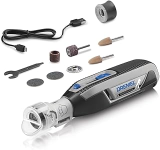
01
Technical snapshot
- Typical material system
- A rigid molded housing may combine with a motor, metal shaft and abrasive element, guard, controls, power interface, and optional flexible isolation parts; final component choices require project validation.
- Typical process route
- Typical routes include housing molding, motor-shaft subassembly, abrasive and guard fit-up, electrical assembly, runout and function review, cleaning review, and packaging.
- Key buyer decision
- Define pet-size range, guard openings, handling posture, speed-control concept, power model, accessory strategy, and cleaning method before detailed design.
02
Reference variant observation
The image presents a pen-shaped handheld unit beside a cable, cap, several cylindrical tips, flat discs, and small accessory tools.
The image is a market-reference input. Visible form may inform planning, but it does not confirm material, construction, performance, ownership or compliance.
Planning questions
- Which alternative visible form or layout should be carried into the comparison brief?
- Which visible interface or presentation detail needs a side-by-side sample review?
03
Material options
Material comparison
| Material selection | Typical material system | Trade-offs |
|---|---|---|
| Rigid molded ergonomic housing | A molded polymer housing may integrate grip geometry, controls, vents, guard interfaces, and service features, with resin, wall, texture, and assembly selected by project. |
|
| Metal shaft and abrasive interface | A metal shaft and project-selected abrasive assembly may provide the rotating working interface, with alignment, retention, guard clearance, and replacement method confirmed by sample. |
|
04
Manufacturing route
- 01
Define handling posture, guard geometry, working interface, control model, and power architecture for sampling.
- 02
Mold housing and guard parts with controlled locating, vent, seam, and service features.
- 03
Assemble motor, shaft, abrasive element, controls, power parts, and optional isolation components.
- 04
Review rotation, runout, vibration, acoustic behavior, guard access, control sequence, cleaning, and packaging.
05
Design for manufacturing
- Motor and shaft locating features should control concentricity without relying only on housing clamp force.
- Guard openings and clearances should balance working access, visibility, debris flow, and unintended-contact risk.
- Grip seams, controls, vents, and service joints should avoid pressure points and debris traps in the intended hand positions.
06
Quality controls
- Risk
- Shaft runout or abrasive imbalance may increase vibration, noise, and inconsistent contact.
- Control point
- Use approved runout and assembled-operation checkpoints on representative motor-shaft assemblies.
- Risk
- Loose guards or housing joints may alter clearances or create rattling.
- Control point
- Verify fastener or snap engagement, guard clearance, and housing seam consistency after assembly.
- Risk
- Debris entering vents or service joints may affect maintenance and appearance.
- Control point
- Review debris paths during representative use and confirm accessible cleaning points and final-style instructions.
07
Customization scope
- Dimensions, capacity, and component layout
- Color, surface appearance, and branding position
- Retail packaging, accessory set, and assortment format
08
Buyer checklist
- Confirm the target market, channel, and intended use environment.
- Confirm the pet size range and the required product dimensions or capacity.
- Select the preferred material direction and finish through specification and sample review.
- Define project-specific testing and documentation requirements before tooling or bulk production.
09
Buyer FAQ
Are these materials the confirmed production specification?
No. They are typical engineering options for development reference; final material, construction, testing, and compliance requirements should be confirmed through the approved specification and sample.
What should a buyer confirm before sampling?
Confirm use conditions, dimensions, material direction, cleaning expectations, branding, packaging, and any market-specific testing or documentation needs.
10
Related products
 Pet Slicker Brush · Reference 02
Add this SKU to an inquiry
Typical concepts may include handheld grinders, guarded abrasive heads, rechargeable or corded layouts, and accessory-led grooming sets.
Add this SKU to an inquiry